
High-Speed PCB
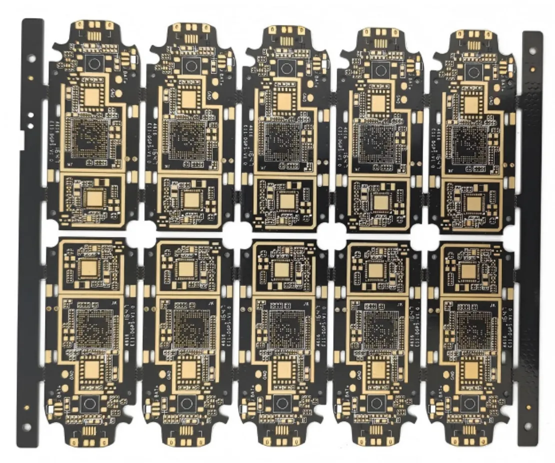
Circuit boards for fast digital interfaces where signal integrity depends on materials, geometry and via design.
High-Speed PCB with ShinePCB
High-speed boards combine low-loss materials, controlled impedance and careful via design. We review your data rates, loss budget and impedance targets with the stack-up, and discuss back drilling where via stubs matter.
- Low-loss material options
- Impedance targets and trace geometry
- Via stubs and back drilling
- Stack-up symmetry and reference planes
Capability and certificates
| Positioning | Low Loss / Controlled Impedance | |
|---|---|---|
| Standard / prototype | Advanced / mass production | |
| High-Speed PCB | Impedance ±5% | Impedance ±7% |
Related certificates
- ISO 9001:2015133628
- UL 796E466435
- IECQ QC 080000IECQ-H NQAGB 25.0038
Source: ShinePCB capability workbook, navigation overview. Values are confirmed against your files and the assigned facility during engineering review; certificates are available on request.
High-speed capability
| Parameter | Prototype | Mass production |
|---|---|---|
| Layer count (max) | 24L | 20L |
| Impedance tolerance | ±5% | ±8% |
| Trace width tolerance | ±0.6 mil | ±1 mil |
| Layer registration | 2 mil | 3 mil |
| Max aspect ratio | 16:1 | 12:1 |
| Hole copper uniformity | COV ≤ 5% | COV ≤ 7% |
| Warpage | 0.50% | 0.75% |
| Special processes | POFV (VIPPO), sequential lamination, local lamination, long/short gold finger, counterbore, back drill, side metallization, N+N structure, edge plating, thick copper, HDI | Same processes as prototype |
| Rigid — Layer count (max) | 48L | 36L |
| Rigid — Impedance control tolerance | ±5% | ±7% |
Source: ShinePCB capability workbook (high-frequency & high-speed sheet; rigid PCB 2025 values). Prototype and mass-production values are listed separately and are not interchangeable. Every value is confirmed against your files, the selected material and the assigned facility during engineering review.
Low-loss laminates
| Material | Series | Tg | Dk | Df | Typical use |
|---|---|---|---|---|---|
| Panasonic MEGTRON 6 | High-speed digital | 185 °C | 3.34 @ 13 GHz | 0.0037 | High-speed multilayer |
| Panasonic MEGTRON 7 R-5785(N) | High-speed digital | 200 °C | 3.31 @ 14 GHz | 0.0023 | High-speed multilayer; backplane |
| Panasonic MEGTRON 8 R-5795(N) | Ultra-high-speed digital | 220 °C | 3.13 @ 14 GHz | 0.0016 | High-speed multilayer; backplane |
| Panasonic MEGTRON 8 R-5795(U) | Ultra-high-speed digital | 220 °C | 3.08 @ 14 GHz | 0.0012 | High-speed multilayer; backplane |
| Panasonic XPEDION 1 R-5515X | Low-loss epoxy | 170 °C | 3.06 @ 14 GHz | 0.0021 | High-speed multilayer |
| TUC TU-872SLK / TU-933 | High-speed low-loss | — | — | — | High-speed multilayer; backplane |
| Ventec VT-770 / VT-770LK | High-speed digital | — | 3.18–3.41 @ 10 GHz | 0.0039–0.0045 | High-speed digital (varies with construction) |
| Shengyi Synamic 6 / 6N / 6GX | High-speed digital | — | 3.35–3.73 | 0.0021–0.005 | High-speed digital |
| Nelco N4000-13 series | High-speed low-loss | — | — | — | High-speed backplane and multilayer |
Source: ShinePCB capability workbook, material sheet. Dk, Df and Tg are typical supplier datasheet values (test frequency shown where the source lists it). They describe the laminate, not the finished board. Grades are available on request and confirmed with availability during engineering review. "—" means no value is listed in the source.
Typical applications
Servers
storage and accelerators
Networking and switching equipment
Test and measurement hardware
From prototype to production
Every order follows the same controlled sequence. Prototype and production requirements are reviewed separately.
File review
Gerber or ODB++, drill data, drawing and quantities are checked for completeness.
Engineering questions
Open points on manufacturability, materials or special processes are sent before quotation.
Stack-up and material
Construction, laminate and finish are confirmed with you and written into the order.
Fabrication
The order is released to the facility whose process and qualification fit the requirements.
Inspection and test
Inspection and electrical test follow the methods agreed for your order.
Packing and delivery
Boards are packed and shipped under the confirmed delivery terms.
What to send for a PCB review
Start with the details you have — engineering will request anything else needed for the review.
Files and details for a PCB review
- Gerber (RS-274X) or ODB++ data with drill files
- Fabrication drawing with material, thickness and finish
- Stack-up and impedance targets, if any
- Quantity for prototype and for production
- Special requirements such as IPC class, testing or packaging
Technical files stay private
Customer Gerber, BOM and design data are managed under an ISO/IEC 27001 information security system and shared only within your project.
High-Speed PCB FAQs
Do you test impedance?
The impedance test method is agreed with the order during review.
Can you help reduce loss?
Engineering can review material and geometry options against your loss budget. No performance value is assumed without project review.